So you need to buy piping for compressed air system, but what about the sizing? Understanding how to properly size pipes for compressed air can improve the overall efficiency of your system. Correctly sized compressed air piping will help you save money and ensure that you always have the PSI you need to run machines and tools at the ends of your lines. Here’s how to determine the right diameter compressed air pipes for your system.
How Pipe Size Impacts Compressed Air System Performance
Sizing air compressor piping comes down to two factors: how much air are you trying to move? And how far does it have to go? When compressed air pipes are not sized properly, you can experience significant pressure drop across your system.
What Happens When Compressed Air Pipes Are Too Small?
When compressed air moves through your piping system, friction with the pipe causes it to lose pressure (PSI) as it travels—a phenomenon known as pressure drop. The smaller the pipe, and the longer the distance the air travels, the more friction it experiences and the more it slows down. That translates to greater pressure drop. Pressure drop also increases with every bend, join and coupling in your piping system. When you are pushing air through too-small pipes with many bends and couplings, you can experience a significant loss of pressure between the air compressor and the ends of the lines.
When compressed air piping is too small, you may have to increase the overall PSI of your system to compensate. Ideally, you should see no more than a 3 PSI drop between pressure at your air compressor and pressure at the point of use at the end of your compressed air line. If you are experiencing excessive pressure drop, you will have to raise the PSI of your system so that all of your machines and tools continue to work properly. This can drive up energy costs for your air compressor significantly. If equipment at the ends of your lines required 100 PSI, and you experience a 20 PSI drop between the compressor and point of use, you will have to pressurize your system to 120 PSI just to maintain your minimum required PSI. That translates to a 10% increase in energy costs for your air compressor. Over time, these increased energy costs will be many times greater than the cost of new piping.
Aire Tip: A 2 PSI increase in plant pressure increases energy costs by about 1%.
What Happens When Compressed Air Pipes Are Too Big?
Oversized compressed air pipes do not have any negative impacts on system performance, but they may be a poor capital investment. Larger compressed air pipes will require more materials and cost more to install than a piping system with smaller pipes.
Larger pipes store more air; 500 feet of 1” pipe will store about 18 gallons of air, while 500 feet of 2” pipe will store about 77 gallons. This is not the most efficient way to store air; if air storage is your primary consideration, it is much more cost-effective and efficient to simply buy more or larger air receiver tanks.
It might be worth it to invest in a larger system than you currently need if you are planning to expand in the future. Installing somewhat oversized compressed air pipes now will be more cost-effective than tearing out and replacing your piping system later.
How Compressed Air Piping is Sized
To avoid excessive pressure drop, you need to look at two important aspects of your compressed air system:
- Total airflow (CFM)
- Minimum required operating pressure (PSI)
Compressed Air Pipe Size and CFM
Compressed air piping size requirements are directly related to the maximum airflow going through the system. Your airflow is measured in cubic feet of air per minute, or CFM. The greater your CFM, the larger your pipes will need to be to avoid excessive pressure drop.
When sizing compressed air piping, it is important to look at your maximum CFM requirements. This is the CFM of your system at moments of greatest demand. These may be momentary peaks of demand generated by dust collector blow-down valves, cylinder/ram actuation, diaphragm pumps or other systems that use short, intense bursts of air.
Aire Tip: Processes that require short-duration (<1 min.), intense bursts of air may be able to be accommodated by installing an air receiver tank at the point-of-use instead of increasing pipe size throughout your system.
Calculating CFM requirements for your facility can be somewhat complicated. You may want to have a study completed to calculate your overall CFM demand, peak demand and maximum air compressor output. Read more: How to Calculate Air Compressor CFM and Production Requirements.
Compressed Air Pipe Size and PSI
You also need to understand the minimum required operating pressure for your system. Your operating pressure is measured in pounds per square inch, or PSI. Most industrial equipment and air-powered tools require between 90 and 100 PSI to operate correctly. That means that the pressure delivered at point-of-use must be maintained at this level.
You can determine the pressure drop for your system by measuring PSI at the air compressor and at the point of use. Be sure to measure the pressure at the points most distant from your air compressor. If you are seeing a drop of more than 3 PSI and do not have a significant leak problem in your system, it may be an indicator that your air compressor piping is too small.
Aire Tip: Many plants are running at a higher PSI than they need. You may be able to save money by lowering the overall pressure of your plant. Read more: Reduce Plant Pressure to Save Money and Energy.
Other Factors in Compressed Air Pipe Sizing
Pressure drop is also related to compressed air piping material and the length of your runs. As we explained above, the longer the run, the more friction air will experience, and the more pressure is lost. Longer runs will require a larger diameter pipe than shorter runs (see tables below).
The material of the pipe also impacts friction and pressure drop; smooth materials like aluminum allow greater airflow than rubber hosing, for example. Read more: What is The Best Piping Material for Compressed Air Systems?
The flow coefficient of your pipe is a measure of its efficiency in allowing air or fluid flow. It is expressed mathematically as:
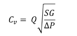
where:
Q is the rate of flow (expressed in US gallons per minute),
SG is the specific gravity of the fluid (for air = 1),
ΔP is the pressure drop across the valve (expressed in psi).
The layout of your compressed air distribution system also matters. Loop-type compressed air systems allow the air to flow in any direction to get to the demand in the path of least resistance. Typically, you can multiply the capacity of straight-line piping by 1.5 for loop type compressed air distribution systems. For example: If a 2” aluminum pipe is rated for 500 CFM at 125 PSI, that same length of pipe in a loop system would be rated for 750 CFM at 125 PSI.
Compressed Air Pipe Sizing Calculation
There are many tools available to help you with compressed air pipe sizing. You can calculate your pipe size requirements using a formula. You can also find tables online that show the CFM ratings of compressed air through traditional pipe based on PSI and distance.
When calculating compressed air sizing requirements, be sure to look at both current and future needs. If your calculation puts you at the upper range of the CFM ratings for a particular pipe size, you may want to consider sizing up, especially if you anticipate an expansion in the future. Also, remember to consider the number of turns and connections in your compressed air system; if your system has many joins and turns, you need to take that into account when calculating your compressed air piping size.
Compressed Air Pipe Sizing Formula
The basic formula for calculating compressed air pipe size is:

Where:
A = the area of a cross-section of the pipe bore in square inches (3.14 x diameter squared/4)
Q = Flow rate in SCFM
Pa = Prevailing absolute pressure in PSI (sea level is 14.7)
Pd = Compressor gauge pressure minus prevailing absolute pressure
V = Design pipe velocity ft/sec (would not be more than 40 ft/sec)
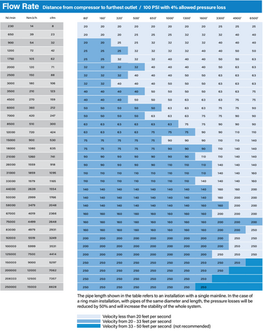
Compressed Air Pipe Sizing Chart
If that calculation looks daunting, don’t worry. There are also tables that can help you determine the right air compressor pipe diameter based on your CFM and the total length of the pipe in your compressed air system. Here are the steps to determine correct compressed air pipe sizing using the chart.
- Determine the max CFM for your system.
- Draw a piping schematic that includes all of the lengths of pipe and all of the fittings, valves and bends in your piping system.
- Measure and add together all of the straight runs in the piping system in feet.
- Then, add in some extra “equivalent length” for each bend, fitting or valve. As a general rule of thumb, you can add 5’ in length for every bend or tee. For a more accurate estimate, use the “Equivalent Length of Pipe for Pipe Fittings” table (Table 2 below).
- Add your total length and equivalent lengths of fittings together to get your total “Equivalent Length of Pipe” for your system.
- Using the Max CFM and Equivalent Length of Pipe, use Table 1 below to find the recommended pipe diameter for your compressed air system.
- Need help determining the right diameter of compressed air piping for your system? We can help you with compressed air pipe sizing and system design. Contact us to get started. Chicago (847) 678-8788 – Minneapolis (612) 712-2781 – Milwaukee (414) 895-5523
- ©2024 Fluid-Aire Dynamics, Inc. All Rights Reserved.
